Table of Contents
Introduction
This is the first part of a series about building an FM radio from scratch in C, without using any third-party library.
That means no librtlsdr, and no libusb either. Everything talks to the hardware through the Linux kernel’s own USB interface, which is a file and a system call.
Which also means everything here is Linux-only. And if you are still on Windows, take a moment to ask yourself why, after all these years of abuse, you are still there.
This part is the groundwork: finding the dongle, taking it away from the driver, and getting to the point where we can read and write the chip’s registers.
You can find the full source code here.
The hardware
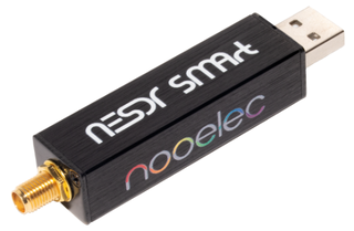
The device we will be talking to is a Nooelec NESDR SMArt v5, a USB dongle that covers radio frequencies from $100$ kHz to $1.75$ GHz with up to $3.2$ MHz of instantaneous bandwidth.
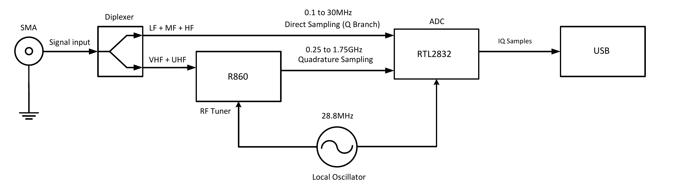
Block diagram from the NESDR SMArt v5 datasheet
Inside it there are two chips:
The first is the Rafael Micro R820T2 tuner. It is the analog front end: it takes whatever the antenna picks up across most of that range and mixes the slice we care about down to a fixed intermediate frequency.
The second is the Realtek RTL2832U, a demodulator and USB interface. It digitizes the intermediate frequency coming out of the tuner and streams the resulting samples to the host over USB.
Fun fact: the RTL2832U was built to receive DVB-T television. Eric Fry noticed in 2010, and Antti Palosaari confirmed in 2012, that it can also be told to skip the TV decoding and hand over the raw I/Q samples instead. Steve Markgraf then wrote the driver that turned that into something usable, which is how a TV receiver became the cheapest SDR around.
Finding the USB device file
In Linux, almost everything is a file, including USB devices.
Running lsusb shows us that the USB dongle is on bus 3 as device 10:
$ lsusb
Bus 003 Device 010: ID 0bda:2838 Realtek Semiconductor Corp. RTL2838 DVB-T
So we can reach it through the file /dev/bus/usb/003/010.
This path is not stable. Device numbers are handed out at plug time, so they move around.
We need an identifier that belongs to the device itself instead of one the kernel hands out. lsusb already printed it: 0bda:2838, the vendor id and the product id.
Those two are burned into the device. 0bda is Realtek, assigned to them by the USB-IF, and 2838 is the model. If we unplug the USB dongle and move it to another port, it will still answer 0bda:2838.
So instead of hardcoding the path, we go looking for the device that answers 0bda:2838. The kernel lists every connected USB device under /sys/bus/usb/devices/, one folder each, with every property inside as its own small text file:
$ ls /sys/bus/usb/devices/3-2/
busnum  devnum  idProduct  idVendor  manufacturer  product  serial  speed  ...

$ cat /sys/bus/usb/devices/3-2/idVendor
0bda
Which makes finding the dongle a one-liner:
$ grep -l 2838 /sys/bus/usb/devices/*/idProduct
/sys/bus/usb/devices/3-2/idProduct
A product id alone is not unique, so we match on both vendor and product. In C that grep becomes a walk over the same folder, reading both attributes per entry and comparing them:
while ((entry = readdir(dir)) != NULL)
{
    read_sysfs_attr(entry->d_name, "idVendor", id_vendor, sizeof(id_vendor));
    read_sysfs_attr(entry->d_name, "idProduct", id_product, sizeof(id_product));

    if (strcmp(id_vendor, "0bda") == 0 && strcmp(id_product, "2838") == 0)
    {
        read_sysfs_attr(entry->d_name, "busnum", busnum, sizeof(busnum));
        read_sysfs_attr(entry->d_name, "devnum", devnum, sizeof(devnum));
        break;
    }
}
read_sysfs_attr just reads a file into a buffer and strips the trailing newline.
Entries whose name contains a colon, like 3-2:1.0, get skipped: those are interfaces rather than devices and do not have these attributes.
An interface is one of the jobs a device does. A webcam has one for video and another for audio.
With the two numbers we can build the path and open it:
snprintf(path, sizeof(path), "/dev/bus/usb/%03d/%03d", atoi(busnum), atoi(devnum));
fd = open(path, O_RDWR);
%03d because the directory names are zero-padded, and O_RDWR because we will be reading from the device and writing to it.
The kernel got there first
Okay, so we have located the USB device file, but it does not mean we get to use it yet.
As far as the kernel is concerned, this is still a television receiver. So when we plugged it in, it went looking for a driver, found dvb_usb_rtl28xxu, and handed the device over to the driver:
$ readlink -f /sys/bus/usb/devices/3-2:1.0/driver
/sys/bus/usb/drivers/dvb_usb_rtl28xxu
That driver is going to decode television for us, which is not what we want. We want the raw I/Q samples, so we need the interface for ourselves.
The usual lazy advice is to blacklist dvb_usb_rtl28xxu in modprobe.d so it never loads.
We will not, since the kernel lets us ask for the interface at runtime: we take it when we start and give it back when we are done.
The asking is done with the ioctl() system call on the USB file we opened.
Kicking the driver off is USBDEVFS_DISCONNECT wrapped in a struct usbdevfs_ioctl together with the interface number.
Drivers bind to interfaces rather than to the device itself, which is why dvb_usb_rtl28xxu turned up on 3-2:1.0. Ours is interface 0.
struct usbdevfs_ioctl cmd = {
    .ifno = 0,
    .ioctl_code = USBDEVFS_DISCONNECT,
    .data = NULL,
};
ioctl(fd, USBDEVFS_IOCTL, &cmd);
Claiming it afterwards is simpler, just the interface number:
unsigned int ifno = 0;
ioctl(fd, USBDEVFS_CLAIMINTERFACE, &ifno);
On the way out we undo both, in reverse. First we drop the claim:
ioctl(fd, USBDEVFS_RELEASEINTERFACE, &ifno);
Then we give the driver back, which is the same wrapped call as before with USBDEVFS_CONNECT in place of USBDEVFS_DISCONNECT:
struct usbdevfs_ioctl reconnect = {
    .ifno = 0,
    .ioctl_code = USBDEVFS_CONNECT,
    .data = NULL,
};
ioctl(fd, USBDEVFS_IOCTL, &reconnect);
Making the device talk
We now own the interface, but we still have not asked the device anything.
Data does not go to a device as such; it goes to one of its endpoints. An endpoint is a numbered channel with a direction, and a device can have several.
Endpoint 0 is the exception. Every device is required to have it, and it works both ways. It is also the only endpoint we can use right now, since we do not yet know what other endpoints this device has.
So we ask the USB dongle to describe itself. The answer is the device descriptor, 18 bytes with the USB version it speaks, its vendor and product ids, and how many configurations it has. The layout is fixed by the USB standard.
The question is always the same shape, five fields:
| field | meaning | for this request |
|---|---|---|
bRequestType | which way the data goes, and who answers | 0x80, device to host, answered by the device itself |
bRequest | which of the standard requests | 0x06, get me a descriptor |
wValue | argument, meaning set by the request | 0x0100, split in two: type 01 for the DEVICE descriptor, index 00 since a device only has one |
wIndex | second argument, same | 0, unused here |
wLength | how many bytes we want back | 18, the size of a device descriptor |
We fill those fields into a struct and hand it to ioctl() again, this time with USBDEVFS_CONTROL. The struct also takes a buffer for the answer and a timeout in milliseconds:
uint8_t buf[18];
struct usbdevfs_ctrltransfer ctrl = {
    .bRequestType = 0x80,
    .bRequest     = 0x06,
    .wValue       = 0x0100,
    .wIndex       = 0,
    .wLength      = sizeof(buf),
    .timeout      = 1000,
    .data         = buf,
};
ioctl(fd, USBDEVFS_CONTROL, &ctrl);
The kernel sends it, waits for the reply, and writes it into buf. If we print the buffer we can see the 18 bytes:
Device descriptor (hex): 12 01 00 02 00 00 00 40 da 0b 38 28 00 01 01 02 03 01
Every byte in there has a fixed place. The interesting bytes:
| byte | value | meaning |
|---|---|---|
| 0 | 12 | length of the descriptor, 18 |
| 1 | 01 | descriptor type, 1 for DEVICE |
| 2-3 | 00 02 | USB version, 2.00 |
| 7 | 40 | 64, the biggest packet endpoint 0 takes |
| 8-9 | da 0b | vendor id, 0x0bda |
| 10-11 | 38 28 | product id, 0x2838 |
| 17 | 01 | how many configurations it has, 1 |
The vendor id reads backwards on purpose: da 0b is 0x0bda, low byte first, because USB puts multi-byte values little endian.
Finding the endpoint where the samples come out
The device descriptor told us what the device is, but not how to move data in or out of it. Endpoints are not mentioned in there.
They sit one level down. A device holds configurations, a configuration holds interfaces, and an interface lists its endpoints:
device
└── configuration
    └── interface
        └── endpoint
That last byte of the device descriptor, the byte saying one configuration, was the top of this tree. So the next question is: give me that configuration.
This configuration descriptor is not a fixed size like the device descriptor. It comes back as a chain: the configuration itself, then the interface, then one descriptor per endpoint, packed one after another in a single blob.
Which leaves us not knowing how many bytes to ask for. The tidy way is to ask twice, first for the 9-byte header to read wTotalLength out of it, then for that many bytes. We will just hand it a 255-byte buffer and let it send whatever it has.
The request is the same as before with a different wValue, type 02 for CONFIGURATION:
uint8_t cfg[255];
struct usbdevfs_ctrltransfer ctrl = {
    .bRequestType = 0x80,
    .bRequest     = 0x06,
    .wValue       = 0x0200,
    .wIndex       = 0,
    .wLength      = sizeof(cfg),
    .timeout      = 1000,
    .data         = cfg,
};
ioctl(fd, USBDEVFS_CONTROL, &ctrl);
What comes back is 25 bytes, three descriptors back to back:
Config descriptor (hex): 09 02 19 00 01 01 04 80 fa 09 04 00 00 01 ff ff ff 05 07 05 81 02 00 02 00
| bytes | length | type |
|---|---|---|
09 02 19 00 01 01 04 80 fa | 9 | configuration |
09 04 00 00 01 ff ff ff 05 | 9 | interface |
07 05 81 02 00 02 00 | 7 | endpoint |
Every descriptor begins the same way, its own length then its type, which is all we need to walk the chain: read the length, jump that far, look at the type, repeat.
The endpoint descriptor is what we came for:
| byte | value | meaning |
|---|---|---|
| 0 | 07 | length, 7 bytes |
| 1 | 05 | descriptor type, 5 for ENDPOINT |
| 2 | 81 | in binary 1000 0001: the top bit is the direction, 1 for IN, and the bottom four bits are the number, so this is endpoint 1, IN |
| 3 | 02 | transfer type, 2 for bulk |
| 4-5 | 00 02 | little endian again, low byte first, so 0x0200, which is 512 bytes per packet |
Directions are named from the host’s point of view, so IN means into the PC. The samples the dongle sends us arrive on an IN endpoint.
Bulk means no timing guarantee but everything is checked and resent if it gets corrupted.
So 0x81 is where the samples will come out. The rest of this post is about learning to talk to the RTL2832U itself, which is what it will take to get it pushing samples into that endpoint.
Reading and writing registers
Every request so far came from the USB standard, which has nothing to say about radios.
To power on the demodulator, set a frequency, or set a sample rate, we have to configure the RTL2832U itself, and all of that is writing into the chip’s registers.
The addresses and the request shape below come from the RTL2832U datasheet, in its register description sections. Realtek never meant it for the public. It was marked for development partners only, but a copy is not hard to find online.
Registers are reached with vendor commands, the same struct usbdevfs_ctrltransfer as before with different values in the fields. The two calls below are what rtl_read_reg and rtl_write_reg wrap in the source.
wIndex carries two things: which part of the chip we are addressing, which the datasheet calls the block, and whether we are reading or writing. Reading from the system block is 0x0200 and writing to it is 0x0210. The datasheet lists seven blocks in all.
wValue is the register address.
The register DEMOD_CTL controls the demodulator. The datasheet puts it at offset 0 of the system block, whose addresses start at 0x3000, so its address is 0x3000.
uint8_t value;
struct usbdevfs_ctrltransfer ctrl = {
    .bRequestType = 0xc0,   // vendor request, device to host
    .bRequest     = 0,
    .wValue       = 0x3000, // DEMOD_CTL
    .wIndex       = 0x0200, // read from the system block
    .wLength      = 1,
    .timeout      = 1000,
    .data         = &value,
};
ioctl(fd, USBDEVFS_CONTROL, &ctrl);
0xc0 is device to host like 0x80 was, but vendor instead of standard.
The register reads back as 0x20. In binary that is 0010 0000, and the datasheet gives a meaning to each bit; the ones that matter here:
| bit | meaning | ours |
|---|---|---|
| 7 | demodulator PLL | off |
| 6 | ADC I enable | off |
| 5 | hardware reset, 1 releases it | released |
| 3 | ADC Q enable | off |
The PLL and both ADCs are off.
Writing is the same call with two changes: bRequestType becomes 0x40, and wIndex gains 0x10, so writing to the system block is 0x0210 instead of 0x0200. The value goes out in the data stage.
Turning the demodulator on means setting the PLL bit and both ADC bits, leaving the reset released. From the table above that is 1110 1000, or 0xe8.
Reading the register back afterwards:
DEMOD_CTL = 0xe8
  demodulator PLL on
  ADC I           on
  hardware reset  released
  ADC Q           on
The demodulator is running.
Where we are
The program finds the dongle on any port, takes the interface from the kernel driver and gives it back on exit, reads the descriptors, works out which endpoint carries the samples, and reads and writes chip registers. The demodulator is powered on.
It still cannot tune. We have rtl_read_reg and rtl_write_reg, but we do not know what most of the registers do.
The next part is about the chip itself: what is actually inside the dongle, why the tuner cannot be reached directly, and how you work out what to write to a chip whose datasheet was never meant to leave the building.
By the end of it, this stops being a television receiver.