Table of Contents
Introduction
This is the second part of a series about building an FM radio from scratch in C, without using any third-party library.
The hardware is an RTL-SDR dongle made of two chips. The R820T2 tuner is the analog part: it brings the radio signal down in frequency. The RTL2832U is the digital part: it turns the signal into samples and sends them to the PC over USB.
Part 1 covered talking to the RTL2832U over USB: finding the dongle, taking it from the kernel driver, and reading and writing the chip’s registers. This part sets up the RTL2832U until it sends raw I/Q samples.
The RTL2832U has no public documentation, so we follow the writes librtlsdr makes, and use the comments in the Linux kernel driver to understand them.
You can find the full source code here.
Register access
Each register of the RTL2832U is addressed by three things: a block, a page, and an address.
Each block is a separate part of the chip. librtlsdr numbers them from 0 to 6:
| block | name | function |
|---|---|---|
0 | Demodulator | signal processing: mode, filter, sample rate |
1 | USB | the endpoint that sends samples to the host |
2 | System | power, clock and reset of the demodulator |
3 | Tuner | not used by librtlsdr or the kernel |
4 | ROM | not used by librtlsdr or the kernel |
5 | IR | infrared receiver for a remote control |
6 | I2C | the bus to the tuner chip |
The demodulator has more than 256 registers, but its register address is only one byte. So its registers are split into pages of 256.
We reach these registers with the USB control transfer from part 1. The block and the page go in wIndex, and the address goes in wValue. For example, reading DEMOD_CTL in the system block:
struct usbdevfs_ctrltransfer ctrl = {
    .bRequestType = 0xc0,
    .bRequest     = 0,
    .wValue       = 0x3000, // DEMOD_CTL
    .wIndex       = 0x0200, // read from the system block
    .wLength      = 1,
    .timeout      = 1000,
    .data         = &value};
wIndex is 16 bits, which is four hex digits. Each digit is a separate field:
| digit | field | meaning |
|---|---|---|
| 3 | unused | |
| 2 | block | which part of the chip |
| 1 | access | 1 to write, 0 to read |
| 0 | page | which page, demodulator only |
So the 0x0200 above reads from block 2, the system block, at page 0, and 0x0210 writes to it.
Every block other than the demodulator leaves the page at 0.
Therefore building wIndex is done with this function:
static uint16_t reg_windex(uint8_t block, uint8_t page, int write)
{
    return (uint16_t)((block << 8) | (write ? 0x10 : 0x00) | (page & 0x0f));
}
wValue contains the address. For the demodulator, the address goes in the high byte and the low byte is always 0x20, as librtlsdr does in rtlsdr_demod_read_reg:
static uint16_t reg_wvalue(uint8_t block, uint16_t addr)
{
    return (block == DEMODB) ? (uint16_t)((addr << 8) | 0x20) : addr;
}
rtl_read_reg and rtl_write_reg are the backbone of this article. They wrap the USB control transfer and use reg_windex and reg_wvalue to fill wIndex and wValue.
Every register holds one byte, so wLength is 1. A value wider than one byte is split over registers at consecutive addresses.
To read, bRequestType is 0xc0, a vendor request from the device (the dongle) to the host (the PC):
int rtl_read_reg(rtl_dev *dev, uint8_t block, uint8_t page, uint16_t addr, uint8_t *out)
{
    struct usbdevfs_ctrltransfer ctrl = {
        .bRequestType = 0xc0,
        .bRequest = 0,
        .wValue = reg_wvalue(block, addr),
        .wIndex = reg_windex(block, page, 0),
        .wLength = 1,
        .timeout = 1000,
        .data = out};

    int ret = ioctl(dev->fd, USBDEVFS_CONTROL, &ctrl);
    if (ret < 0)
    {
        fprintf(stderr, "Failed to read register 0x%04x of block %u page %u: %s\n",
                addr, block, page, strerror(errno));
    }
    return ret;
}
To write, bRequestType is 0x40, a vendor request from the host (the PC) to the device (the dongle), and data holds the byte to write:
int rtl_write_reg(rtl_dev *dev, uint8_t block, uint8_t page, uint16_t addr, uint8_t val)
{
    struct usbdevfs_ctrltransfer ctrl = {
        .bRequestType = 0x40,
        .bRequest = 0,
        .wValue = reg_wvalue(block, addr),
        .wIndex = reg_windex(block, page, 1),
        .wLength = 1,
        .timeout = 1000,
        .data = &val};

    int ret = ioctl(dev->fd, USBDEVFS_CONTROL, &ctrl);
    if (ret < 0)
    {
        fprintf(stderr, "Failed to write register 0x%04x of block %u page %u: %s\n",
                addr, block, page, strerror(errno));
    }
    return ret;
}
Both return the number of bytes transferred, so 1 on success.
Powering on the demodulator
librtlsdr powers on the demodulator with two writes to the system block: DEMOD_CTL_1 = 0x22 and DEMOD_CTL = 0xe8.
The kernel’s USB driver, rtl28xxu.c, names the bits of DEMOD_CTL in its comments:
| bit | kernel comment | in plain words |
|---|---|---|
| 7 | “enable PLL” | Start the clock. Digital logic only moves on clock ticks, and the PLL (phase-locked loop) makes that clock from the crystal. |
| 6, 3 | “enable ADC” | Power the ADC (analog-to-digital converter), which turns the signal into samples. |
| 5 | “disable reset” | While reset is on, the demodulator is stopped. |
0xe8 is 1110 1000: PLL on, ADC on, reset released.
No public source explains DEMOD_CTL_1, so we cannot decode 0x22.
We then define our power-on function as:
int rtl_power_on(rtl_dev *dev)
{
    if (rtl_write_reg(dev, SYSB, 0, DEMOD_CTL_1, 0x22) != 1 ||
        rtl_write_reg(dev, SYSB, 0, DEMOD_CTL, 0xe8) != 1)
    {
        return -1;
    }
    return 0;
}
Switching to SDR mode
After powering on the demodulator, librtlsdr switches it from TV mode to SDR mode with a series of writes, each with a comment:
| page | register | value | librtlsdr comment | in plain words |
|---|---|---|---|---|
| 1 | 0x01 | 14, then 10 | “reset demod” | |
| 1 | 0x15 | 00 | “disable spectrum inversion and adjacent channel rejection” | Keep the spectrum as is, not mirrored, and stop filtering out neighboring TV channels. |
| 1 | 0x16–0x1b | 00 | “clear both DDC shift and IF frequency registers” | Set the digital down-converter (DDC) shift and the intermediate frequency (IF) to 0 Hz. |
| 0 | 0x19 | 05 | “enable SDR mode, disable DAGC” | Send raw I/Q samples over USB instead of decoded TV data. Turn off digital automatic gain control (DAGC). |
| 1 | 0x93 0x94 | f0 0f | “init FSM state-holding register” | Set the starting value of an internal finite state machine (FSM). No source says what it controls. |
| 1 | 0x11 | 00 | “disable AGC” | Turn off automatic gain control (AGC), which keeps the signal level constant. |
| 1 | 0x04 | 00 | “disable RF and IF AGC loop” | Stop the demodulator from controlling the tuner’s RF and IF gain. |
| 0 | 0x61 | 60 | “disable PID filter” | Turn off the packet ID (PID) filter, which passes only the packets of selected TV streams. |
| 0 | 0x06 | 80 | “default ADC_I/ADC_Q datapath” | |
| 1 | 0xb1 | 1b | “Enable Zero-IF mode, DC cancellation, IQ estimation/compensation” | Expect a zero-IF input, centered on 0 Hz. Remove the DC offset and correct the I/Q imbalance. |
| 0 | 0x0d | 83 | “disable 4.096 MHz clock output on pin TP_CK0” |
Our rtl_set_sdr_mode makes the same writes, in the same order:
static const struct
{
    uint8_t page, addr, val;
} sdr_mode[] = {
    {1, 0x01, 0x14}, {1, 0x01, 0x10},
    {1, 0x15, 0x00},
    {1, 0x16, 0x00}, {1, 0x17, 0x00},
    {1, 0x18, 0x00}, {1, 0x19, 0x00},
    {1, 0x1a, 0x00}, {1, 0x1b, 0x00},
    {0, 0x19, 0x05},
    {1, 0x93, 0xf0}, {1, 0x94, 0x0f},
    {1, 0x11, 0x00},
    {1, 0x04, 0x00},
    {0, 0x61, 0x60},
    {0, 0x06, 0x80},
    {1, 0xb1, 0x1b},
    {0, 0x0d, 0x83},
};

int rtl_set_sdr_mode(rtl_dev *dev)
{
    for (size_t i = 0; i < sizeof(sdr_mode) / sizeof(sdr_mode[0]); i++)
    {
        if (rtl_write_reg(dev, DEMODB, sdr_mode[i].page, sdr_mode[i].addr, sdr_mode[i].val) != 1)
        {
            return -1;
        }
    }
    return 0;
}
Loading the low-pass filter
librtlsdr also writes a filter to page 1, registers 0x1c to 0x2f. The filter works on the samples coming out of the ADC, before the chip lowers the sample rate.
It is a FIR filter: each output sample is the sum of the last 32 input samples, each multiplied by a coefficient.
librtlsdr sends 16 coefficients. The other 16 are the same values in reverse order:
static const int16_t fir_default[16] = {
    -54, -36, -41, -40, -32, -14, 14, 53,
    101, 156, 215, 273, 327, 372, 404, 421};
The first 8 coefficients take one byte each. The last 8 need 12 bits each, so they are packed in pairs: two coefficients in three bytes. That makes 20 bytes, written to page 1 from 0x1c to 0x2f:
int rtl_set_fir(rtl_dev *dev)
{
    uint8_t fir[20];

    for (uint16_t i = 0; i < 8; i++)
    {
        fir[i] = (uint8_t)fir_default[i];
    }

    /* Join each pair of 12-bit values, abc and def in hex, into abcdef, then
     * split it into the bytes ab cd ef. */
    for (int k = 0; k < 4; k++)
    {
        const uint32_t pair = (uint32_t)(fir_default[8 + 2 * k] & 0xfff) << 12 |
                              (uint32_t)(fir_default[9 + 2 * k] & 0xfff);

        fir[8 + 3 * k] = (uint8_t)(pair >> 16);
        fir[9 + 3 * k] = (uint8_t)(pair >> 8);
        fir[10 + 3 * k] = (uint8_t)pair;
    }

    for (uint16_t i = 0; i < 20; i++)
    {
        if (rtl_write_reg(dev, DEMODB, 1, 0x1c + i, fir[i]) != 1)
        {
            return -1;
        }
    }

    return 0;
}
USB setup
librtlsdr starts its bring-up with three writes to the USB block. They set up endpoint 0x81, where the samples come out.
The kernel’s USB driver, rtl28xxu.c, names each write in its comments:
| register | bytes | kernel comment | in plain words |
|---|---|---|---|
USB_SYSCTL | 09 | “enable DMA and Full Packet Mode” | Turn on DMA (direct memory access): a dedicated circuit copies the samples to the endpoint as they arrive. Send only full packets. |
USB_EPA_MAXPKT | 00 02 | “set EPA maximum packet size to 0x0200” | EPA (endpoint A) is endpoint 0x81. Each packet carries up to 512 bytes. |
USB_EPA_CTL | 10 02 | “streaming EP: set stall & reset” | EP is endpoint. Pause it (stall) and empty its queue of waiting samples (reset). |
0x0200 is 512, the packet size of endpoint 0x81 from part 1, stored low byte first: 00 02.
Our rtl_init_usb makes the same writes:
int rtl_init_usb(rtl_dev *dev)
{
    if (rtl_write_reg(dev, USBB, 0, USB_SYSCTL, 0x09) != 1 ||
        rtl_write_reg(dev, USBB, 0, USB_EPA_MAXPKT, 0x00) != 1 ||
        rtl_write_reg(dev, USBB, 0, USB_EPA_MAXPKT + 1, 0x02) != 1 ||
        rtl_write_reg(dev, USBB, 0, USB_EPA_CTL, 0x10) != 1 ||
        rtl_write_reg(dev, USBB, 0, USB_EPA_CTL + 1, 0x02) != 1)
    {
        return -1;
    }
    return 0;
}
rtl_init runs the whole bring-up in librtlsdr’s order:
int rtl_init(rtl_dev *dev)
{
    if (rtl_init_usb(dev) != 0 ||
        rtl_power_on(dev) != 0 ||
        rtl_set_sdr_mode(dev) != 0 ||
        rtl_set_fir(dev) != 0)
    {
        return -1;
    }

    printf("RTL2832U initialized, SDR mode on\n");
    return 0;
}
Setting the sample rate
A resampler in the chip turns samples at the crystal frequency, 28.8 MHz, into samples at the rate we ask for. librtlsdr sets it with the ratio between the two rates, written to page 1 from 0x9f to 0xa2.
The ratio $R = 28.8\text{ MHz} / f_s$ is stored as a fixed-point number with 22 fractional bits, $N = \lfloor R \cdot 2^{22} \rfloor$. For 2.048 MS/s, $R = 14.0625$ and $N =$ 0x03840000.
Our rtl_set_sample_rate does the same:
int rtl_set_sample_rate(rtl_dev *dev, uint32_t rate)
{
    if (rate <= 225000 || rate > 3200000 || (rate > 300000 && rate <= 900000))
    {
        fprintf(stderr, "Unsupported sample rate: %u Hz\n", rate);
        return -1;
    }

    /* crystal ticks per sample, with 22 fractional bits */
    const uint32_t ratio = (uint32_t)(((uint64_t)RTL_XTAL_HZ << 22) / rate) & 0x0ffffffc;

    if (rtl_write_reg(dev, DEMODB, 1, 0x9f, ratio >> 24) != 1 ||
        rtl_write_reg(dev, DEMODB, 1, 0xa0, (ratio >> 16) & 0xff) != 1 ||
        rtl_write_reg(dev, DEMODB, 1, 0xa1, (ratio >> 8) & 0xff) != 1 ||
        rtl_write_reg(dev, DEMODB, 1, 0xa2, ratio & 0xff) != 1 ||
        /* 0 ppm correction */
        rtl_write_reg(dev, DEMODB, 1, 0x3f, 0x00) != 1 ||
        rtl_write_reg(dev, DEMODB, 1, 0x3e, 0x00) != 1 ||
        /* soft reset */
        rtl_write_reg(dev, DEMODB, 1, 0x01, 0x14) != 1 ||
        rtl_write_reg(dev, DEMODB, 1, 0x01, 0x10) != 1)
    {
        return -1;
    }
    return 0;
}
Starting the stream
librtlsdr starts the stream by writing USB_EPA_CTL twice: stall and reset, which empties the queue, then 00 00, which unpauses the endpoint. Our rtl_start_stream does the same:
int rtl_start_stream(rtl_dev *dev)
{
    if (rtl_write_reg(dev, USBB, 0, USB_EPA_CTL, 0x10) != 1 ||
        rtl_write_reg(dev, USBB, 0, USB_EPA_CTL + 1, 0x02) != 1 ||
        rtl_write_reg(dev, USBB, 0, USB_EPA_CTL, 0x00) != 1 ||
        rtl_write_reg(dev, USBB, 0, USB_EPA_CTL + 1, 0x00) != 1)
    {
        return -1;
    }
    return 0;
}
The samples come out of endpoint 0x81 in bulk transfers, the USB transfer type for large blocks of data. Linux exposes them through the USBDEVFS_BULK ioctl, which takes a struct usbdevfs_bulktransfer:
int rtl_read(rtl_dev *dev, uint8_t *buf, unsigned int len)
{
    struct usbdevfs_bulktransfer bulk = {
        .ep = (unsigned int)dev->bulk_in_ep,
        .len = len,
        .timeout = 1000,
        .data = buf};

    int ret = ioctl(dev->fd, USBDEVFS_BULK, &bulk);
    if (ret < 0)
    {
        fprintf(stderr, "Failed to read samples: %s\n", strerror(errno));
        return -1;
    }
    return ret;
}
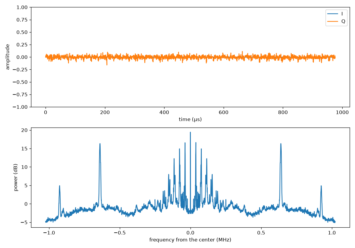
We save one second at 2.048 MS/s to a file and plot it with plot.py, I and Q over time on top and the spectrum below:
Where we are
The RTL2832U is up: powered on, in SDR mode, and streaming samples at the rate we ask for.
The samples carry no FM yet, because the tuner isn’t set up. Part 3 explains the receiver from the antenna to the I/Q samples, and sets up the tuner.